Skip navigation

Monthly Archives: January 2017


In my last update on the robot car, I had successfully setup wifi control for the car but was struggling with a few issues that need attention.  The first issue was the startup behavior of the car.  On boot, the right motor would spin really fast for a few seconds.  While not a huge deal, it was annoying.  The other issue is that the car seemed to be really underpowered, to the point where it wouldn’t even move when driving on carpet.

My assumption regarding the boot behavior was that one of the pins was getting pulled high (or low?) on boot, which was causing the motor to spin.  The motor spinning by itself wasn’t a huge issue, but it was pulling a lot of current which caused problems when I was plugged into a laptop to load code (the laptop would do an emergency shutoff of power to the USB port).  TO protect against these power surges, I decided it would be a good idea to add a second power switch to the car that I could use to control the motors.  This would allow me to load code onto the esp8266 without having to worry about what the motors would do.

Once I had the switch wired up I switched focus to figuring out how to stop the wierd motor behavior.  I went back to my old trusty debugging methods and pulled a second WeMos out of the part box and an LED.  I loaded the Arduino sketch and proceeded to re-boot the WeMos with the LED connected to each pin.  It turns out the D4 pin was getting pulled high on boot, and that was also one of the pins that I was using for motor control.  I went back to the robot car and swapped out the D4 pin for a different one, and was happy to see the weird motor issue disappear!

Testing the pin behavior with an LED

Once I had the boot behavior issue sorted out, and I turned my attention to the motor speed issue.  One thing that I thought was curious was that the weird boot issue caused the motor to spin really fast, but when I operate the car normally, the motors spin pretty slow.  I played around with the control logic and tested out the speed settings of the motor control board but was only having marginal luck getting the motors to power the car.  It would move really slow on hardwood, and would budge a little bit.

After some internet research, I came to a rough conclusion that the motor board controller was throttling the power to the motors to protect them from damage (which is part of the reason you should use the board) and combined with the low power battery source, the friction from the tank treads (the treads ended up being a  pretty tight fit) and the fact the motors are cheap toy motors, the robo car was struggling to move on rough surfaces.  At some point I will test these assumptions so that I can solve the issue, but after tweaking the code a little bit I was able to get the car to move (albeit very slowly) on the carpet and decided to call it a day.

While digging around on the internet for ideas for my first 3D printer project, I stumbled across some bike modifications that looked cool.  It just so happens that I have a two bikes that are in need of repair.  One bike has a flat tire and the other has an out-of-true back wheel and a few broken spokes.  After reading up a bit more on the mechanics of 3D printing and digging around for some designs, I settled on two files and cleared out one of my Saturdays to attempt the print.

The first print is a spoke wrench.  While these are typically made of metal, I figured I would be able to use this to tighten up and tune some spokes with the tool and then use a normal wrench if I needed more tension.  Plus, this particular object looks like a very beginner friendly print.  I settled on this design.   Before getting started, I spent the morning watching some you tube videos.  This particular series by youtube user ‘Life and Times of Tyler‘ was very helpful. It covered all the basics of getting setup with the Monoprice printer, and he has a lot of very useful advice that I found lacking in a lot of other online tutorials.

After watching some of the videos, I came up with a game plan.  I did a much more through bed leveling attempt this time around (not that that was an issue the with the test print, but just wanted to be safe), and I replaced the scotch tape on the print bed with some painters tape that I had ordered online (the scotch tape that came with the printer was already bubbling after the first print).  I loaded up the spoke wrench STL file into CURA (a program that takes design files and then converts that file into a series of instructions for your printer) and tweaked the setting based on Tyler’s advice.  Because this was a pretty simple part, I didn’t have to mess with the orientation or anything more complicated.  I loaded up the CURA file to the SD card, pre-heated the printer, and kicked off the print.

  • Starting the spoke wrench print.

After about an hour I had a pretty cool looking spoke wrench.  Emboldened by my success, I moved on to setting up the bike tire lever print.  I used this design.  I choose this one because it seemed to have a nice balance between simplicity and functionality.  I wanted to have a spoke hook on the lever because those can be very useful when changing tires, but some of the other designs seemed like they would require support material.  Additionally, the lever looked thick enough throughout that it could feasibly handle the stress of the tire change.  So I loaded the STL file into CURA and started playing around with things.  Curiously, the default orientation when I loaded the file was with the lever flat, with the spoke hook angled up into the air.  It seemed like I would need supports enabled for it to print properly, so I enabled that in CURA.  I was a little worried though because Tyler mentioned that he had a lot of trouble getting the supports to come off cleanly from the part.  I figured there were pretty good odds that these tire levers weren’t going to hold up the stresses of real life, so I pushed forward with the print as-is because I figured it would be good to see what how these support structures work.

Sure enough, after the print was done. I attempted to remove the support structures (see photos in slide show) but it was pretty difficult.  I ended up using a razor and file to pull the material off, and in the end still ended up with a very rough surface.  I decided that for the second tire lever, I would print the lever on it’s side which seemed like I could get away with out support material.  Another possible advantage of that orientation was that it could increase strength of the part (3D printers are stronger in the x-y axis, and weaker in the z axis).  So I went back into CURA and made the changes and then kicked off the print.

The second tire lever turned out surprisingly well.  I went online and ordered a new bike tube for one of my bikes.  Once the tube arrived, I got to changing the tire, and I successfully removed the tire without either of the levers breaking.  I did chip one of the levers (the one printed flat) when attempting to put the tire back on (partly my fault, I was hammering it against the tire bead to try and get the bead back in the rim, the lever definitely wasn’t built for that abuse).  So all in all, I consider this little project a success. I could have bought a cheap pair of tire levers online, but it was good to get some more experience with the printer.  Also, I am still waiting for some replacement bike spokes to get shipped, so I will update the blog once I get around to using the spoke wrench.  Cheers!


After getting the electronics working, my next goal was to set up some rudimentary wireless controls for “remote” operation.  I was hoping this would be pretty straight forward because I was using my esp8266 as a microcontroller which has a built in wifi chip but I ran into a few issues along the way.  But after some elbow grease I eventually got the robot to take commands from a remote server.

The first step was to mount the electronics onto the chassis.  This was probably the hardest part of the build so far.  I wasn’t using an off-the-shelf kit, so I had to design the rig on my own (I was able to get some inspiration from the internet).  And because i don’t have a workshop, it is difficult for me to fabricate custom parts/mounting hardware[1].  So I was stuck digging around in my parts box to try and hack something together.  The simple solution would have been to just mount a breadboard directly onto the chassis, but there wasn’t enough room due to the gear box.  After playing around with some different configurations and digging around on the internet, I ordered some standoffs and some prototyping boards from amazon.  I figured I would mount a prototype board on to the chassis using the standoffs to create a ‘double decker’ of sorts.

Of course, the mounting holes on the prototype boards were too small for the standoffs that I had ordered.  It turns out the one of the pieces of the proto-snap mini bot (that I had scavenged some parts from) had mounting holes that worked with the standoffs.  On top of that, it had a ‘blank’ section of PCB that I could attach a small breadboard to, so I settled on that configuration.  I ended up being pretty happy with this configuration, because I was able to rest the esp8266 and the motor controller on the thru-hole section of the PCB, and then use the breadboard to wire everything up.  It is a pretty tight fit, but it is stable enough and because I didn’t have to solder anything, I can easily test different configurations until I settle on a more permanent setup.

Once I had the PCB mounted, I used double sided tape to attach the battery holder on top of the gearbox and I wired up a on/off switch onto the breadboard.  I ran a few tests to make sure that things were wired up correctly and then switched focus to the Arduino code.

  • I set the robot up with a elevated breadboard to allow for quick prototyping.

One of the cool features of the esp8266 is the possibility of doing Over the Air (OTA) updates to the microcontroller.  Normally when you make changes to the code you have to plug your connect your microcontroller to your computer via USB to make the update.  This can be annoying if your microcontoller is mounted in a hard to access area.  So I was excited to try out OTA on this project.  When using the Arduino IDE, you simply add some OTA code to your script which allows future updates to be delivered OTA.

Unfortunately, OTA wasn’t really working for me.  I had tested OTA updated on a bare WeMos and got it working, but I couldn’t get it to work with the robot car.  I didn’t spend a lot of time looking into the issue.  My guess is that either the battery power was too weak to allow for a re-boot/update while connected to all the other electronics on the car (wifi is a big power hog), or the OTA code was conflicting with some of the other code I had in my Arduino script.  I tabled this issue for now and will follow up when I have some more time.

In order to control the robot car, I wrote some code to send http commands to the esp8266 from my computer.  The esp8266 was setup as an http server.  It parses the parameters of any  incoming GET request which then sends the appropriate signals to the motors (forward, left, right, back, and speed).  On my computer, I wrote a little python script that sends http requests based on keyboard input.  After a few tweaks and bug fixes, I got everything to work and was successfully controlling the robot car from my computer.

While the car was technically working, I still have a lot of work ahead of me.  The robot is very slow and underpowered, to the point where it can barely move on carpet.  I tired playing around with the speed control on the motor controller, but didn’t have any luck improving it. So this is something I need to look into.  Also, the robot has a weird startup behavior.  On boot, the left motor spins really fast for a few seconds (and the funny thing is, its a very fast spin, if only I could get it to do that during normal operation than I could drive it on carpet!  Ugggh, hardware!).  My guess is that it has something to do with a few pins getting set high (or low) on boot.  So I will need to look into that as well.

Anyways, the progress has been good so I am happy.  Once I get some of the issues hammered out and clean up the code I will post that to Github, as well as add some follow up posts.

[1] You may have seen my previous post on getting a 3D printer.  The hack session that I am writing about in this post pre-dates that event by a month or two (I often start writing the drafts of these posts soon after the event/topic that I am writing about, but don’t get around to finishing/publishing them for a few weeks or more, so the timelines are bit out of whack here.).  So yes, I now have a 3D printer, and that would have helped quite a bit in building out this bot.  But I am also 3D noob, so it will probably be a few months before I can take full advantage of it.

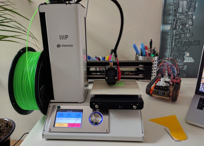
I hope everyone had a Merry Christmas! I was rather surprised to find a 3D printer under the tree this year.  My girlfriend went in with some of my family and got me a MP Select Mini 3D Printer.  While the gift wasn’t totally unexpected as I had dropped a few hints, even at ~$220 it was well out of the range of what my family normally spends on gifts (hence the group effort).  And while I thought it would be cool to own one, I admittedly don’t have a ton of immediate uses for it and found it difficult to justify the impulse purchase considering I live in a pretty small apartment and space is at a premium.  But in the spirit of the excessive and unnecessary consumption that typically accompanies this wonderful holiday, I suppose I can allow myself to indulge a little bit in this unexpected surprise. All things considered, I imagine I will get more use out of the 3D printer than the more typical oversized sweaters and sheet sets that tend to get tossed into the closet only to be donated to goodwill a few years later.

I don’t have a lot of (any) experience with 3D printers, so I am not even going to attempt to review or provide any sort of significant feedback on this thing.  If that is what you are looking for, then I would recommend this rather excellent review of the printer on Hackaday.  In short, the MP Select appears to be a great starter printer that provides comparable performance to printers that are even 3x more expensive.  So if you are looking to dip your toes into the 3D printer market, it sounds like this is probably the best printer to start with.

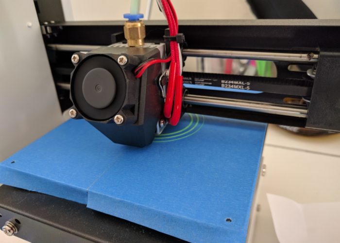
I was able to get the printer up and running fairly quickly.  The printer comes mostly pre-calibrated (not really sure what that means), the only calibration required of the user is to level the bed.  I followed the bed leveling instructions (involves adjusting the four screws holding the print bed in place, and using a sheet of paper to set the gap between the print-head and the bed).  A quarter-turn of each of the screws was all that was required[1].

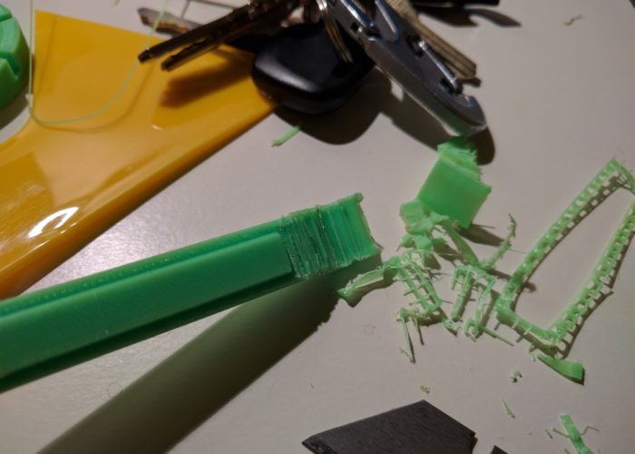
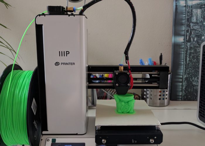
My gf and family were prescient enough to also get me a few spools of PLA filament (the printer comes with a very small amount of test filament, but not enough to do anything significant).  So I set up the appropriate temperatures (still not sure what bed temperature to use, but 50 C seemed to work).  The printer comes with an SD card that already has some test print files on it, so I loaded that up and kicked off a test print.  However, I immediately noticed an issue.  As the printer head was moving into position, filament was ‘leaking’ from the head.  So traces of printed material were getting dragged around the print area and creating a nice little mess of things.  After a quick internet search, I decided to lower the print-head temperature by 10 degrees, and that seemed to do the trick, and I kicked off the test print.

  • Test print getting started!

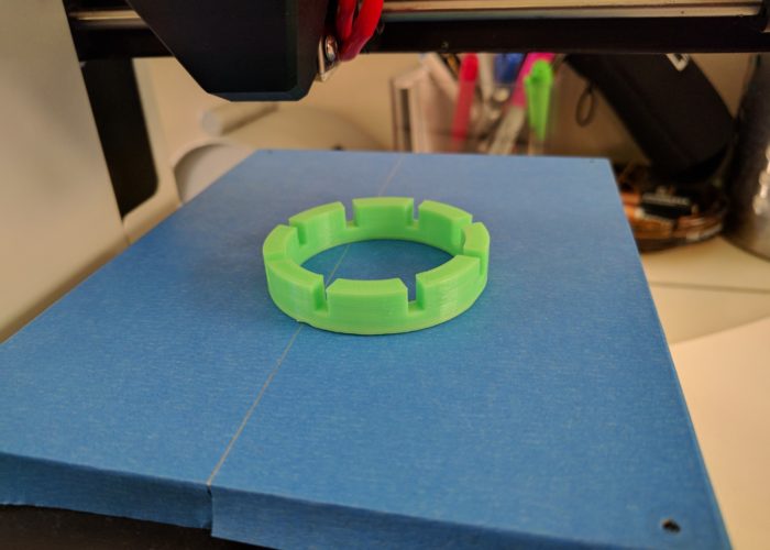
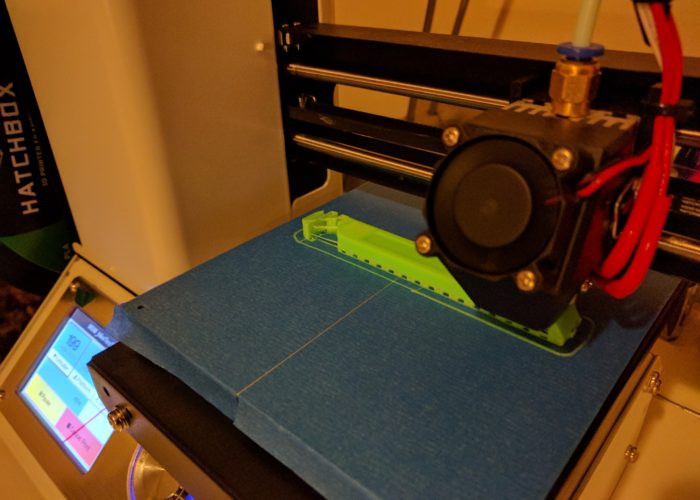
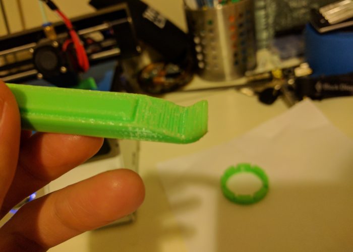
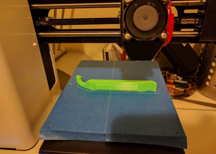
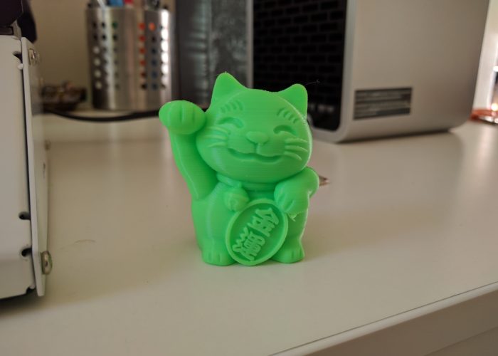
The test print took about 3 hours, and seemed to go perfectly fine.  At one point during the print, I got a little panicked as the printer seemed to be printing material in the ‘wrong’ area, and it was creating a little bit of a mess.  But it turns out, the printer was attempting to print the paw of the cat, which hangs over the belly, and after a few passes in that area, the base of the paw eventually formed and the print carried on unaffected.  If you read the hackaday review, it sounds like this model of printer has some issues with printing overhangs and bridges (areas of a print where there is no material underneath).  This is partly due to the lack of a second cooling fan on the printing head (but is an issue with current 3D printers in general).  If you look closely at the photo in the slideshow, you can see some errant material under the paw.

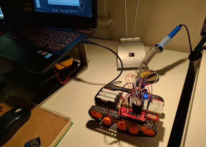
Another concern I had was with the air quality in the room.  There have been a few studies and articles on the topic, and it was one of the reasons I was hesitant to splurge on a printer in the first place.  As I live in a small apartment, I don’t have a lot of options for places to put the printer.  For this test print, I figured I would go ahead and print in my living room so I could keep an eye on it.  And sure enough, about half-way into the print, there was a very distinct ‘plasticy’ smell that filled the room (and this was with windows open and an air purifier running nearby).  Assuming I am not printing 24/7, the emissions are most likely tolerable (probably not too dissimilar to the VOC risks from your soldering iron), but this is a very new technology so we don’t really have any way to know for certain what the long term impacts are, so it is probably best to air on the side of caution.  So for future prints, I am thinking I will either put the printer in our garage (which is a little tricky cuse it’s a shared garage for our partment) or build an enclosure with a filtration system.

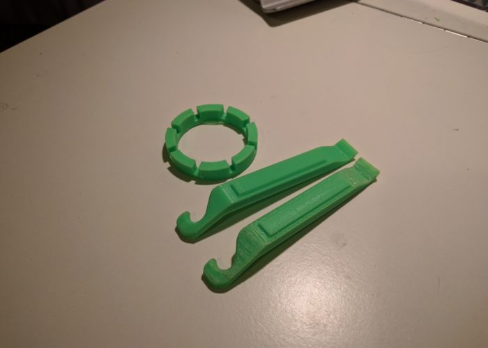
With that disclaimer out of the way, I can confidently say that this little 3D printer is pretty awesome, and I am excited to put it to use on some of my projects.  I don’t have any concrete plans at the moment, but I will most likely start by making a few project enclosures and other simple items/trinkets. But it would be cool to eventually print some parts for a robot or some other mechanical pieces for projects (one of the downsides to living in a small apartment is I don’t have a workshop that allows for fabrication, so in theory, a printer could help fill that gap a little bit). Anyways, I am looking forward to what the new year has in store, and I will keep you posted on any developments. Cheers and Happy 2017!

[1] I am a little concerned about the simplicity of their leveling instructions.  You set the printer head to ‘home’ (which puts the head on one corner of the bed) and then they have you use a piece of printer paper as a proxy for 0.05 mm spacing measurement.  So you adjust the bed until you can slide the piece of paper between the printer-head and the bed.  But it seems to me that if you don’t evenly adjust all four corners of the bed, or if the bed was already a little ‘un-level’, than you wouldn’t have a level bed. (i.e. I feel that you either need to have the print head move to all four corners, and then do the ‘paper adjustment’ on each corner, or you need to use a leveler tool to adjust the bed (although that would level the bed based on gravity, and not necessarily to the orientation of the printer (i.e. if the table the printer sits on is a little unlevel, that would cause issues).  Anyway, going off on a tangent here.  This is something I should probably follow up on a little, but my test print came out fine, so probably not a big deal.