After getting the electronics working, my next goal was to set up some rudimentary wireless controls for “remote” operation. I was hoping this would be pretty straight forward because I was using my esp8266 as a microcontroller which has a built in wifi chip but I ran into a few issues along the way. But after some elbow grease I eventually got the robot to take commands from a remote server.
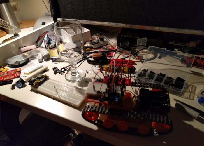
The first step was to mount the electronics onto the chassis. This was probably the hardest part of the build so far. I wasn’t using an off-the-shelf kit, so I had to design the rig on my own (I was able to get some inspiration from the internet). And because i don’t have a workshop, it is difficult for me to fabricate custom parts/mounting hardware[1]. So I was stuck digging around in my parts box to try and hack something together. The simple solution would have been to just mount a breadboard directly onto the chassis, but there wasn’t enough room due to the gear box. After playing around with some different configurations and digging around on the internet, I ordered some standoffs and some prototyping boards from amazon. I figured I would mount a prototype board on to the chassis using the standoffs to create a ‘double decker’ of sorts.
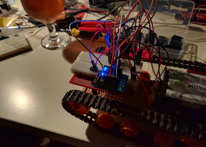
Of course, the mounting holes on the prototype boards were too small for the standoffs that I had ordered. It turns out the one of the pieces of the proto-snap mini bot (that I had scavenged some parts from) had mounting holes that worked with the standoffs. On top of that, it had a ‘blank’ section of PCB that I could attach a small breadboard to, so I settled on that configuration. I ended up being pretty happy with this configuration, because I was able to rest the esp8266 and the motor controller on the thru-hole section of the PCB, and then use the breadboard to wire everything up. It is a pretty tight fit, but it is stable enough and because I didn’t have to solder anything, I can easily test different configurations until I settle on a more permanent setup.
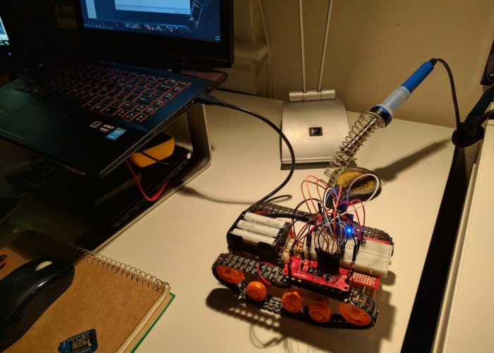
Once I had the PCB mounted, I used double sided tape to attach the battery holder on top of the gearbox and I wired up a on/off switch onto the breadboard. I ran a few tests to make sure that things were wired up correctly and then switched focus to the Arduino code.
-
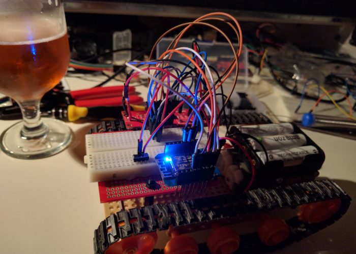
 I set the robot up with a elevated breadboard to allow for quick prototyping.
One of the cool features of the esp8266 is the possibility of doing Over the Air (OTA) updates to the microcontroller. Normally when you make changes to the code you have to plug your connect your microcontroller to your computer via USB to make the update. This can be annoying if your microcontoller is mounted in a hard to access area. So I was excited to try out OTA on this project. When using the Arduino IDE, you simply add some OTA code to your script which allows future updates to be delivered OTA.
Unfortunately, OTA wasn’t really working for me. I had tested OTA updated on a bare WeMos and got it working, but I couldn’t get it to work with the robot car. I didn’t spend a lot of time looking into the issue. My guess is that either the battery power was too weak to allow for a re-boot/update while connected to all the other electronics on the car (wifi is a big power hog), or the OTA code was conflicting with some of the other code I had in my Arduino script. I tabled this issue for now and will follow up when I have some more time.
In order to control the robot car, I wrote some code to send http commands to the esp8266 from my computer. The esp8266 was setup as an http server. It parses the parameters of any incoming GET request which then sends the appropriate signals to the motors (forward, left, right, back, and speed). On my computer, I wrote a little python script that sends http requests based on keyboard input. After a few tweaks and bug fixes, I got everything to work and was successfully controlling the robot car from my computer.
While the car was technically working, I still have a lot of work ahead of me. The robot is very slow and underpowered, to the point where it can barely move on carpet. I tired playing around with the speed control on the motor controller, but didn’t have any luck improving it. So this is something I need to look into. Also, the robot has a weird startup behavior. On boot, the left motor spins really fast for a few seconds (and the funny thing is, its a very fast spin, if only I could get it to do that during normal operation than I could drive it on carpet! Ugggh, hardware!). My guess is that it has something to do with a few pins getting set high (or low) on boot. So I will need to look into that as well.
Anyways, the progress has been good so I am happy. Once I get some of the issues hammered out and clean up the code I will post that to Github, as well as add some follow up posts.
[1] You may have seen my previous post on getting a 3D printer. The hack session that I am writing about in this post pre-dates that event by a month or two (I often start writing the drafts of these posts soon after the event/topic that I am writing about, but don’t get around to finishing/publishing them for a few weeks or more, so the timelines are bit out of whack here.). So yes, I now have a 3D printer, and that would have helped quite a bit in building out this bot. But I am also 3D noob, so it will probably be a few months before I can take full advantage of it.