Skip navigation

Monthly Archives: October 2016

A few nights ago I got around to putting together a tank chassis for what will eventually become some sort of robot tank.  I am still not 100% sure what the goals are for the robot.  I know I want to be able to control it over wifi, and I will most likely have some form of distance measuring sensors for obstacle detection.

A few years ago I had ordered a MiniBot kit from sparkfun.  I wrote a few posts on some of my experiences with the kit, but the tldr was that the FTDI chip on the board was faulty, and while Sparkfun was nice enough to send out a replacement, it was a long while (due to my own procrastination and some other obstacles) before I actually had a working bot.  During that period, I had been ordering some parts here and there for planned upgrades to the bot (it was designed to be very customizable, which was cool).  After a while, I realized that I had enough parts to build a second bot from scratch (in part thanks to the faulty board that originally came with the kit, some of the components were salvageable).  So I figured, instead of chopping up the working MiniBot, why not just build a second one and have two!

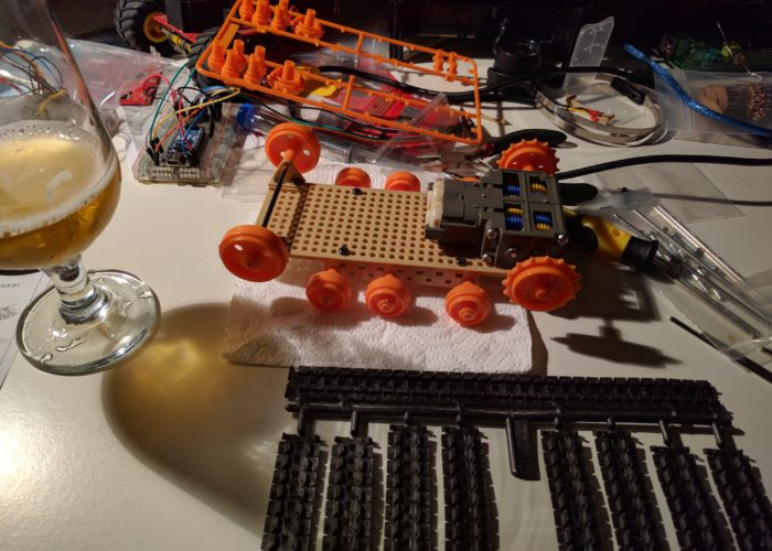
The first step in building a tank robot is to setup the chassis.  An RC company called Tamiya sells some parts that make this pretty straight forward.  Here is a list of parts that I used, you can find these on Sparkfun, Amazon, and a number of other websites:

  • Tamiya 70168 Double GearBox
  • Tamiya 70098 Universal Plate
  • Tamiya 70100 Track and Wheel set

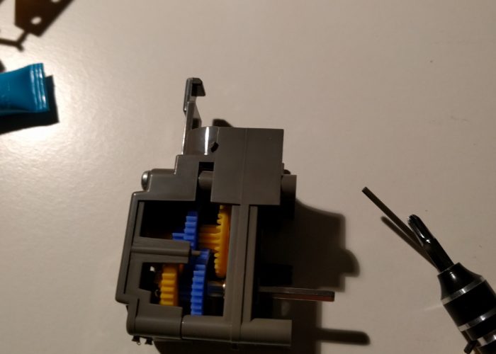
The first is a gear box which allow us to transfer power from the electric motors to the wheels.  If you are unfamiliar with electric motors and you have a few hours to kill, I would recommend doing some reading on the topic as it is pretty fascinating.  But in short, for most motors, especially the ones you are likely to find on hobby robots, you need some type of power transfer system.  Hooking the motors up directly to the wheels will result in burning your motors out.

The gearbox assembly was a bit complicated, but not necessarily difficult.  The tricky part is that you need to have all of the drive shafts and gears lined up properly before you can tighten down the housing to hold things in place.  So it might take a few attempts, but once you get a sense of how the gears are supposed to fit together, it is pretty straight forward.

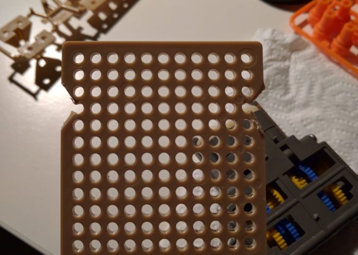
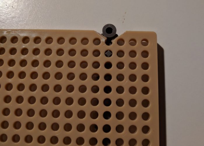
The universal plate is a nice mounting option for your gearbox as well as the the track and wheel set.  Tamiya clearly designed these three parts so that they would work together.  For some reason the latest version of the twin gear box was widened such that the mounting holes are now wider than the plate set.  The downside is you now have to make some cuts to the plate set and use a mounting adapter (included with the gearbox) in order to mount the gearbox. I’m sure there is a reason for it, but seems like an odd design choice considering these three components were clearly meant to work together.
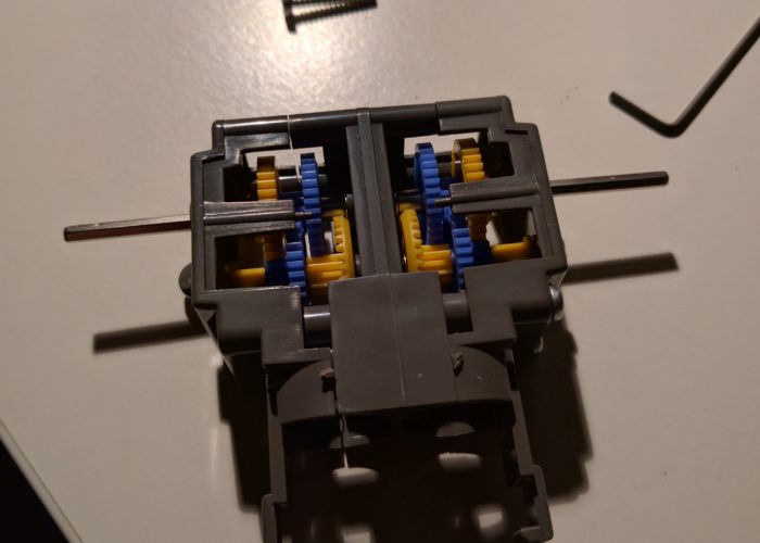
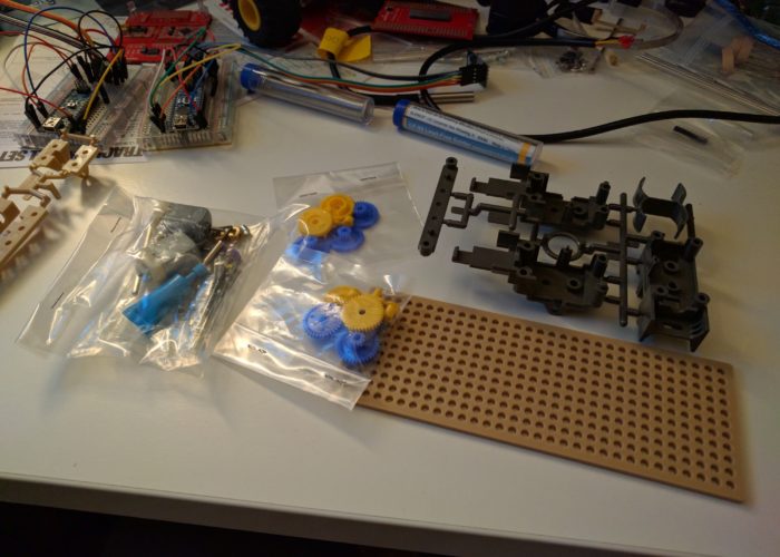
  • The gear box parts!

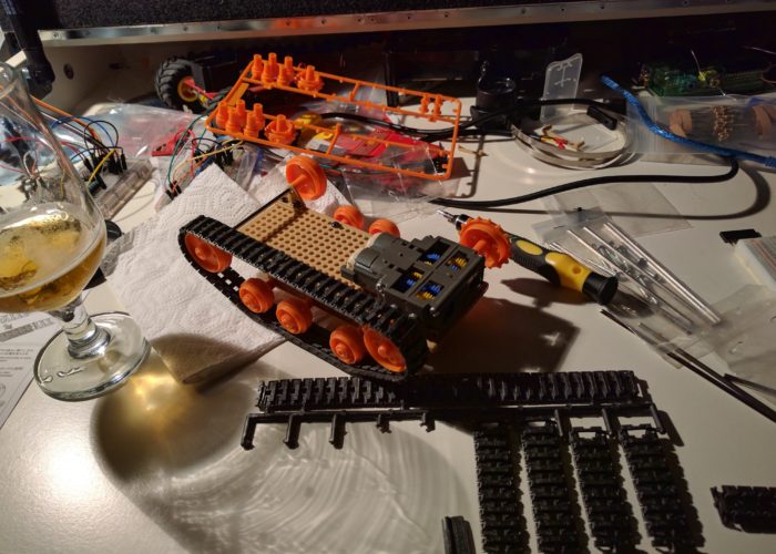
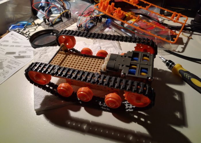
Once the gearbox was mounted to the plate set, I mounted the track and wheel set.  I dug around online to see what some of the possible configurations were, and I think I settled on the best configuration that requires the least amount of custom modifications (see the slideshow for the configuration).  Depending on the electronics that you plan to use and your ability to build/modify parts, you may want to change the design up.  For example, this robot configuration seems to be a fairly space efficient configuration that doesn’t require too many modifications to the parts.

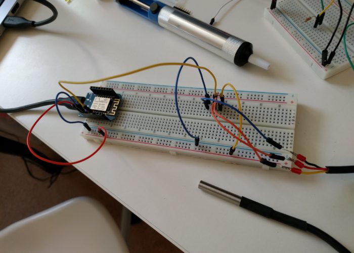
Now that I have the robot chassis assembled, my next task is to start getting some control electronics working.  The plan for now is to prototype on a breadboard, and then if possible, either mount the breadboard, or move the components over to a prototype board.  Either way I am looking forward to getting the robot up and running.  My cat needs someone(thing) to keep her company during the day!

In my previous post, I discussed some of the ‘fun’ that I have had working on hardware projects, and in this post I will be pushing that meme forward a bit.

One of the few successful projects that I have managed to pull off was a temperature sensor to monitor my homebrew fermentations.  I had a few of these units set up, and they would monitor the fermentation temperature as well as the ambient temperature and send the data to a server.  While the project sounds pretty simple, I had hacked together a fairly complex solution (temp sensor hooked up to an arduino hooked up to a Raspberry Pi) because sending data over wifi from an arduino usually requires buying a rather expensive shield (basically an add-on board for the arduino).  One of my goals after finishing the project was to revisit better ways to send the data.

A few months after I had finished the temp sensor project, a little board called the esp8266 started to get some buzz on the interwebs.  The board was made by a company in China called Espressif and it was getting a lot of attention because it was a fairly cheap microcontroller that had built in wifi.  At the time, they were hard to get a hold of and they were poorly documented, so I decided to explore some different wireless options and wait to see how things would play out regarding the esp8266.

After about 6 months, a community started to build around the esp8266 and development boards were being offered by a number of different companies.  I hadn’t made much progress on the temp sensor project thanks to the usual distractions, so I figured I would order up a few development boards (WeMos).  After I received the boards, I read through some tutorials to figure out the best (re: easiest) development setup (a few different solutions were available to program the board, some more complicated than others).  I decided to try out using the Arduino IDE with the esp8266 addon as I was already familiar with that environment.

Once I had the esp8266 addon installed, getting the WeMos to run the blink sketch using the onboard LED was pretty straightforward, which was encouraging.  Next, I started playing around with some of the boards Wifi capabilities.  I found a sketch online that connected the board to an access point, and also scanned and printed out a list of accessible wireless networks.  After a few fits and starts (not 100% sure what the issue was, but seems like you need to reset the board before you can upload a new sketch, and possibly unplug and replug the usb/power cable), I got the code uploaded and was happy to see the WeMos reporting back the local wireless networks to my serial monitor.  Now that I had some momentum, I figured I would take a stab at setting up the temperature sensor and see if I could get the WeMos to report the data to one of my servers.

I spent an hour or two cobbling snippets of code together that I had found on the web.  From what I could tell, the Arduino sketch to read data from the temp sensor didn’t need too many modifications to get it to work with the WeMos (which is awesome) so I figured I could use the code that I wrote when I first attempted this project (using arduinos).  After assembling a sketch together I loaded it up and held my breath…

And of course it didn’t work.  This kicked off a round of fruitless troubleshooting.  I stripped the code apart and tested out the pieces individually to see if I could pinpoint the issues.  Turns out I needed to make some modifications to how the data was getting sent to my server, and after some tweaking was able to send some dummy data across the network.  Once I had that bit up and running, I tried loading the temperature sensor portion of the sketch, and while it successfully loaded, I was getting bad data in the serial monitor.  At this point it was getting late, so I decided to head to bed and re-visit the issue at another time.

A few weeks later (I really need to get on a more regular hacking schedule) I carved out some time to work on the project.  While I still wasn’t sure what the issue was, I had a few hunches that I was going to try and test.  In order to help diagnose the issue I also set up an Arduino microcontroller with another temp sensor, so that I could go back and forth between the two to try and better diagnose the issue.

  • Always try the blink sketch. If you can't blink, you have problems.

I tried a few different things to see if I could isolate the issue.  I set up an external power supply on the hunch that the wifi chip in the WeMos was drawing too much current from USB, but that didn’t yield anything (and I think my breadboard power supply was actually not working that well, you get what you pay for!).  I tried out a few different tests like swapping pins (WeMos has different pin layout which doesn’t correspond to the arduino pin layout) as well as testing voltages and currents.  But nothing was yielding any promising results.

In a fit of frustration, I grabbed an led and some jumper wire, and decided to go back to the basics and test out the Blink sketch[1].  If I couldn’t get an LED to blink than I either had a junk module on my hands or I just wasn’t cutout to be a hardware guy.  I set everything up, uploaded the code and … unexpectedly, instead of a nice steady blink, I got a few sputtering flashes. hmm….

To cut to the chase, it turns out you can’t just push some headers through the pinholes of the WeMos to connect it to the breadboard and expect solid contact[2].  In my defense, I had done this before with some other boards and it worked fine, so it’s not like I was being super naive about it (well I kinda was).  After this realization, I pulled the WeMos off the breadboard, and then wedged the LED into the pinholes and …. SWEET!!! It was blinking.

Know that I had a reasonable idea of what the issue was, I set about to soldering some headers to one of the boards.  It was a tight fit, and I may or may not have a few pins that are now connected to each other via some sloppy solder, but I did my best to isolate the pin that I was going to use for the temp sensor, and then popped the board back into the breadboard.

And wouldn’t you know, worked like a charm….

[1] The Blink sketch is the ‘Hello World’ of microcontrollers.  You hook up an LED, and then tell you microcontroller to blink it.  When I initially played around with the board, I had run the blink sketch using the onboard LED, but had not attempted to wire up an external LED.  In hindsight, that should be the first thing you do with any new microcontroller.

[2] The WeMos D1 mini comes without headers soldered onto the board.  But they provide some headers that you can solder on if you need them.  In order to ‘preserve’ the board (headers can be a bit bulky, making the board harder to use in smaller projects) I was just pushing the headers through the pins and then pushing them into the breadboard, and using some pressure to ‘ensure’ contact between the pins and the breadboard.  Turns out I wasn’t really getting any contact.